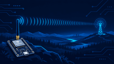



A magnetic reed switch serves as one of the simplest sensors you can integrate with an ESP32. Consequently, it opens the door to real-world home security projects. In this tutorial, you will build a functional door and window alarm that detects when an entryway is opened and instantly sends a free push notification to your phone over Wi-Fi. We will use IFTTT Webhooks to accomplish this without a paid cloud service.
What You Will Learn
- Discover how a magnetic reed switch functions and how to wire it.
- Detect a digital state change (open vs. closed) reliably in Arduino code.
- Trigger a free IFTTT Webhook event directly from the ESP32 over Wi-Fi.
- Receive a custom push notification on your smartphone whenever the door opens.
Project Prerequisites
- Difficulty: Beginner
- Time Required: 25–35 minutes
- Estimated Cost: Under $3 (reed switch) + a free IFTTT account
Components Needed
- 1x ESP32 development board
- 1x Magnetic reed switch module (2-wire or 4-wire digital output type)
- Jumper wires
- Double-sided tape or small screws for mounting the sensor
- A free IFTTT account (ifttt.com) with Webhooks and Notifications services enabled
Circuit Wiring Diagram
Most common reed switch modules feature three pins: VCC, GND, and DO (digital output). Before uploading code, mount one half of the switch on the door frame and the other half directly on the door itself. Ensure they align closely so they touch when the door is closed.
| ESP32 Pin | Connected Component |
| 3.3V | Reed switch module VCC |
| GND | Reed switch module GND |
| GPIO 13 | Reed switch module DO (signal) |
Pro Tip: If you’re using a bare 2-wire reed switch (lacking a module), connect one leg to GPIO 13 and the other directly to GND. Furthermore, you must enable the ESP32’s internal pull-up resistor within your code (
INPUT_PULLUP).
Step-by-Step Setup Guide
Step 1: Create Your IFTTT Webhook Applet
- Log in to ifttt.com and create a new Applet.
- Select the Webhooks service as your ‘If This’ trigger. Then, choose ‘Receive a web request’. Name the event specifically, e.g.,
door_opened. - Choose Notifications → ‘Send a notification from the IFTTT app’ as your ‘Then That’ action.
- Navigate to ifttt.com/maker_webhooks and click Documentation to discover your personal Webhooks key; this is required for the code.
- Install the official IFTTT app on your smartphone and log in.
Step 2: Wire the Hardware Sensor
Connect the reed switch module to your ESP32 exactly as shown in the wiring table provided above. Afterward, physically mount the two sensor halves onto the door and frame.
Step 3: Upload the Door Alarm Code
Copy the full sketch below into your Arduino IDE. Make sure you update your Wi-Fi credentials as well as your unique IFTTT key and event name, and then upload it to your board.
C++
#include <WiFi.h>
#include <HTTPClient.h>

const char* ssid = "YOUR_WIFI_NAME";
const char* password = "YOUR_WIFI_PASSWORD";

const char* iftttKey = "YOUR_IFTTT_KEY";
const char* eventName = "door_opened";

const int reedPin = 13;
bool lastState = HIGH;  // HIGH = closed (magnet present)

void sendNotification() {
  if (WiFi.status() == WL_CONNECTED) {
    HTTPClient http;
    String url = "http://maker.ifttt.com/trigger/" + String(eventName) +
                 "/with/key/" + String(iftttKey);
    http.begin(url);
    int httpCode = http.GET();
    Serial.print("IFTTT response code: ");
    Serial.println(httpCode);
    http.end();
  }
}

void setup() {
  Serial.begin(115200);
  pinMode(reedPin, INPUT_PULLUP);

  WiFi.begin(ssid, password);
  Serial.print("Connecting to WiFi");
  while (WiFi.status() != WL_CONNECTED) {
    delay(500);
    Serial.print(".");
  }
  Serial.println();
  Serial.println("Connected!");

  lastState = digitalRead(reedPin);
}

void loop() {
  bool currentState = digitalRead(reedPin);

  if (currentState == HIGH && lastState == LOW) {
    Serial.println("Door opened! Sending notification...");
    sendNotification();
  }

  lastState = currentState;
  delay(200);
}
Step 4: Test Your Wi-Fi Alarm
- Open the Serial Monitor within Arduino IDE and set the baud rate to 115200 to observe debug messages.
- Open the door where you mounted the sensor. The ESP32 prints ‘Door opened!’ in the console. Consequently, a push notification should arrive on your phone within a few seconds.
- Close and reopen the door multiple times to confirm the alarm triggers consistently.
How It Works
The reed switch contains two metal contacts that close when a magnet is nearby (door closed) and open when the magnet moves away (door opened). The ESP32 continuously reads the digital pin’s state. When it detects a transition from LOW to HIGH, it sends a GET request to a unique IFTTT Webhooks URL. IFTTT receives this request, recognizes your specific event name, and instantly triggers the action—in this scenario, pushing a notification directly to your smartphone app.
Troubleshooting Common Issues
- No phone notification arrives: Double-check your IFTTT key and ensure the event name matches exactly what you configured in the Applet.
- Alarm triggers repeatedly while the door is open: This occurs if you don’t incorporate a debounce or cooldown. Add a simple delay or use a ‘notified’ flag in your code.
- Reed switch always reads HIGH or LOW: Check your magnet alignment. Usually, the magnet must be within approximately 1-2 cm of the sensor to register as closed.
- HTTP request fails consistently: Confirm your ESP32 has actual internet access, rather than just local Wi-Fi connectivity. IFTTT is a cloud-based service.
Next Steps and Project Extensions
- Integrate a local buzzer or high-brightness LED for an audible and visual alarm alongside the smartphone notification.
- Monitor multiple entryways by using several reed switches connected to different GPIO pins.
- Incorporate an ‘arm/disarm’ schedule so the alarm only operates at night or when you are away.
- Combine this sensor with our future smart home MQTT project to build a unified dashboard.
- Check out our related guide on Building a Simple ESP32 Web Server to learn about web-based controls, or review the Official Espressif Documentation to explore pin capabilities further.
Published on iotjournal.net — part of the ‘Practical ESP32 Projects’ series.
For more hardware tutorials and modern embedded technology trends, explore our complete [IoT Magazine] collection.