Every Hardware Protocol Explained: UART, SPI, I2C, CAN, and Beyond

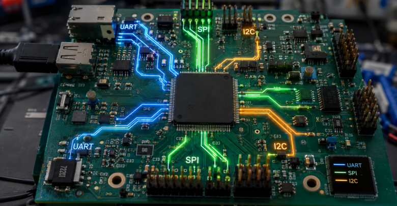
In embedded systems and Internet of Things (IoT) engineering, selecting the right hardware communication protocol dictates system performance, signal integrity, and power efficiency. Microcontrollers like the ESP32 or STM32 must constantly exchange data with sensors, displays, and external peripherals.
This comprehensive guide breaks down the architecture, transmission mechanics, and optimal use cases for every major hardware communication protocol used in modern electronics.
1. Asynchronous Serial Communication: UART
UART (Universal Asynchronous Receiver-Transmitter) is one of the oldest and simplest serial communication protocols. Unlike synchronous interfaces, UART does not utilize a dedicated clock signal line.
       [ Microcontroller A ]                   [ Microcontroller B ]
      +---------------------+                 +---------------------+
      |                 TX  |---------------->| RX                  |
      |                 RX  |<----------------| TX                  |
      | $GND$               |-----------------| $GND$               |
      +---------------------+                 +---------------------+
Key Technical Specs
- Bus Type: Asynchronous, Point-to-Point (2 devices only).
- Signal Lines: $2$ lines (
TXfor Transmit,RXfor Receive) plus a shared $GND$. - Data Transmission: Frames consist of $1$ Start bit, $5$ to $9$ Data bits, an optional Parity bit, and $1$ or $2$ Stop bits.
- Baud Rates: Standard speeds range from $9600$ to $115200$ bps (and higher in specialized SoCs).
Primary Use Cases
Debug logging output, GSM/GPS module interfacing, and direct chip-to-chip serial links over short distances.
2. Fast Synchronous Bus: SPI
SPI (Serial Peripheral Interface) is a high-speed, full-duplex, synchronous bus protocol operating on a master-slave architecture.
Bus Architecture and Signal Lines
- SCLK (Serial Clock): Generated by the Master device to synchronize data bits.
- MOSI (Master Out Slave In): Data line sending bits from Master to Slave.
- MISO (Master In Slave Out): Data line sending bits from Slave to Master.
- CS / SS (Chip Select / Slave Select): Dedicated active-low line per slave device to enable communication.
    +---------------+         +---------------+
    |               |--SCLK-->|               |
    |               |--MOSI-->|               |
    | Master Device |--MISO--<| Slave Device  |
    |               |--CS---->|               |
    +---------------+         +---------------+
Advantages & Trade-Offs
- Pros: Extremely fast (often exceeding $10\text{ MHz} – 80\text{ MHz}$), simple hardware implementation, and low latency.
- Cons: Requires extra GPIO pins for each additional slave device (
CSline scaling issue), and lacks built-in acknowledgment/error checking.
3. Two-Wire Multi-Master Interface: I2C
I2C (Inter-Integrated Circuit), developed by Philips (NXP), solves the pin-count limitation of SPI by routing hundreds of devices through just two shared lines.
Key Characteristics
- SDA (Serial Data): Bidirectional line for data transfer.
- SCL (Serial Clock): Clock line managed by the active Master.
- Pull-Up Resistors: Both
SDAandSCLrequire open-drain pull-up resistors (typically $2.2\text{ k}\Omega$ to $10\text{ k}\Omega$) connected to $V_{CC}$.
               VCC (+3.3V / +5V)
                |          |
               [R]        [R]
                |          |
     SCL -------+----------+-------- (Serial Clock)
     SDA ----------+----------+----- (Serial Data)
                   |          |
               +-------+  +-------+
               |  MCU  |  | Sensor|
               +-------+  +-------+
Speed Classes
- Standard-mode: Up to $100\text{ kbps}$
- Fast-mode: Up to $400\text{ kbps}$
- High-speed mode: Up to $3.4\text{ Mbps}$
I2C relies on unique 7-bit or 10-bit device address framing, enabling up to $127$ unique peripherals on a single bus pair.
4. Industrial & Automotive Networking: CAN Bus
CAN (Controller Area Network) is a robust, differential-bus protocol designed for high-noise automotive and industrial automation environments.
Why CAN Bus Stands Out
- Differential Signaling: Uses
CAN_HandCAN_Llines to reject common-mode electromagnetic interference. - No Master: Message-based priority arbitration prevents frame collisions automatically.
- Built-in Fault Confinement: Automatic CRC validation and hardware frame re-transmission.
For practical microcontroller implementations, review our tutorial on ESP32 Architecture and Pinout Configuration.
5. Hardware Protocol Comparison Table
| Protocol | Lines Required | Max Speed | Topology | Duplex | Best Used For |
| UART | 2 | ~1.5 Mbps | Point-to-Point | Full | Debugging, GPS/GSM Modules |
| SPI | 3 + N (CS) | 80+ Mbps | Master-Slave | Full | Displays, SD Cards, Flash Memory |
| I2C | 2 | 3.4 Mbps | Multi-Master / Multi-Slave | Half | On-board Sensors, RTCs, OLEDs |
| CAN | 2 | 1 Mbps (CAN FD: 5+ Mbps) | Multi-Master Differential | Half | Automotive, Robotics, Industrial |
Practical Code Implementation: Scanning I2C Bus Addresses
To demonstrate peripheral bus interaction, here is an Arduino C++ sketch to detect connected I2C devices automatically:
C++
#include <Wire.h>

void setup() {
  Wire.begin();
  Serial.begin(115200);
  while (!Serial);
  Serial.println("\nI2C Scanner Initialized...");
}

void loop() {
  byte error, address;
  int nDevices = 0;

  for (address = 1; address < 127; address++) {
    Wire.beginTransmission(address);
    error = Wire.endTransmission();

    if (error == 0) {
      Serial.print("I2C device found at address 0x");
      if (address < 16) Serial.print("0");
      Serial.print(address, HEX);
      Serial.println(" !");
      nDevices++;
    }
  }

  if (nDevices == 0) Serial.println("No I2C devices found\n");
  delay(5000);
}
Conclusion
Choosing the correct hardware protocol requires balancing pin availability, transmission speed, noise immunity, and bus complexity. Use SPI for high-throughput bandwidth, I2C for simple low-pin sensor arrays, UART for point-to-point module links, and CAN for reliable industrial environments.
HardwareProtocols #UART #SPI #I2C #CANbus #EmbeddedSystems #Microcontroller #Electronics #IoT #IoTJournal #Engineering #Arduino #ESP32 #HardwareDevelopment