
Building software applications requires robust tools to manage file changes over time. Version control provides a structured mechanism for tracking software revisions, preventing accidental code loss, and streamlining developer collaboration.
Consequently, modern software engineering relies on Version Control Systems (VCS) like Git to maintain code integrity across distributed development teams.
What is Version Control?
Imagine building a website project. Once you complete a stable version, you save it as “Version 1” before adding new features. If you accidentally delete a critical file later, version control allows you to roll back instantly to Version 1 with a single terminal command.
When multiple developers collaborate on a project, version control delivers essential advantages:
- Seamless Code Sharing: Team members add, modify, or delete files without manual communication overhead.
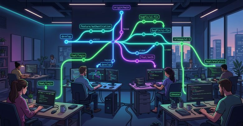
- Safe Concurrent Editing: Multiple engineers can work on the exact same file simultaneously, using smart branching and merging tools to combine changes safely.
- Historical Audit Trail: Developers track every modification, inspect commit history, and identify line-by-line code changes effortlessly.
Why is Git a Distributed Version Control System?
Git operates as a Distributed Version Control System (DVCS). Unlike older centralized systems such as Subversion (SVN), Git does not rely solely on a central server.
Instead, every developer who clones a Git repository holds a full, local copy of the entire project history on their personal computer.
Key Benefits of Distributed Version Control
- No Single Point of Failure: If the main remote server crashes or suffers hardware damage, developers preserve the complete project history. Any engineer can push their local repository copy to a new server to restore the project fully.
- Offline Development Capabilities: Developers commit changes, view historical logs, and create local branches without requiring an active internet connection.
- Faster Operations: Because Git processes history locally on your machine, branch switching, log viewing, and committing execute almost instantaneously.
Centralized vs. Distributed Version Control
The following table summarizes the primary differences between older Centralized VCS and modern Distributed VCS (Git):
| Feature | Centralized VCS (e.g., SVN) | Distributed VCS (Git) |
|---|---|---|
| Project History Location | Central Server Only | Full Copy on Every Developer Machine |
| Offline Work Support | Limited (Requires Server Connection) | Full (Commits and Branching Work Offline) |
| Server Crash Risk | High Risk of Data Loss | Zero Risk (Every Clone Serves as Backup) |
| Execution Speed | Slower (Dependent on Network Latency) | Extremely Fast (Local Processing) |
Conclusion
Compared to legacy centralized systems, Git delivers superior speed, data redundancy, and workflow flexibility. By decentralizing project history and streamlining team collaboration, Git remains the industry-standard version control system for software developers worldwide.