

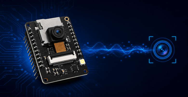
Add a camera to a $6 board, and suddenly a huge range of new projects open up — security cameras, wildlife monitors, doorbell cameras, computer vision experiments. The ESP32-CAM makes this possible: it pairs an ESP32 chip with an OV2640 camera module on a single, inexpensive board.
It’s also one of the trickier ESP32 boards to get started with, mostly because of how you upload code to it. This guide walks through the setup, the quirks, and your first working camera stream.
What Is the ESP32-CAM?
The ESP32-CAM is a small development board built around the ESP32-S chip, with an OV2640 camera module (2 megapixels) attached, along with a microSD card slot for local storage. It includes Wi-Fi and Bluetooth like any ESP32 board, which means it can stream video, serve images over HTTP, or send photos to a cloud service — all without any additional networking hardware.
Because it strips away some of the extra components found on standard ESP32 dev boards (to keep cost and size down), it comes with a few quirks that trip up first-time users. We’ll cover those as we go.
Hardware You’ll Need
- An ESP32-CAM board (widely available, typically $6–10)
- A separate USB-to-serial adapter (like an FTDI or CP2102 module) — the ESP32-CAM does not have a built-in USB port, unlike most other ESP32 dev boards
- Jumper wires to connect the adapter to the board
- A 5V power source capable of at least 500mA (the camera and Wi-Fi radio draw more current than USB alone sometimes provides reliably during flashing)
Wiring the ESP32-CAM for Programming
This is the step that trips up most beginners. Connect your USB-to-serial adapter to the ESP32-CAM like this:
| USB-to-Serial Adapter | ESP32-CAM |
|---|---|
| 5V | 5V |
| GND | GND |
| TX | U0R (RX) |
| RX | U0T (TX) |
You’ll also need to connect GPIO 0 to GND — but only during the upload process. This puts the board into flashing mode. Once the upload finishes, disconnect GPIO 0 from GND and press the reset button to run your program normally.
This two-step dance (connect GPIO 0 to GND to flash, disconnect and reset to run) is the single most common source of “why isn’t this working” frustration with the ESP32-CAM. If your upload fails or the board doesn’t respond, check this connection first.
Setting Up the Arduino IDE
- Install the ESP32 board package in Arduino IDE if you haven’t already (via Boards Manager, searching for “esp32”).
- Under Tools → Board, select “AI Thinker ESP32-CAM” (this is the most common ESP32-CAM variant; check your board’s silkscreen if you’re unsure).
- Under Tools → Partition Scheme, select “Huge APP (3MB No OTA/1MB SPIFFS)” — the camera streaming example needs more program space than the default partition scheme allows.
- Set Upload Speed to 115200 (higher speeds sometimes cause upload failures on this board).
Your First Camera Project: Live Video Streaming
The ESP32 Arduino core includes a built-in example specifically for this board. In Arduino IDE, go to:
File → Examples → ESP32 → Camera → CameraWebServerBefore uploading, you need to make two changes to the sketch:
cpp
// Uncomment the correct camera model — for AI Thinker boards:
#define CAMERA_MODEL_AI_THINKER

// Enter your Wi-Fi credentials
const char* ssid = "YOUR_WIFI_SSID";
const char* password = "YOUR_WIFI_PASSWORD";
Connect GPIO 0 to GND, upload the sketch, then disconnect GPIO 0 and press reset. Open the Serial Monitor at 115200 baud — once the board connects to Wi-Fi, it prints an IP address. Open that IP address in a web browser, and you’ll see a live camera control interface with a “Start Stream” button.
Understanding the Camera Web Server Code
cpp
camera_config_t config;
config.frame_size = FRAMESIZE_UXGA;  // resolution
config.jpeg_quality = 10;             // 0-63, lower means higher quality
config.fb_count = 2;                  // frame buffer count
Frame size controls resolution — higher resolutions look better but use more memory, more bandwidth, and reduce frame rate. JPEG quality works in reverse from what you might expect: a lower number means higher quality (less compression) and a larger file size. For live streaming over Wi-Fi, dropping resolution and increasing compression (raising the jpeg_quality number) usually gives smoother video than pushing for maximum image quality.
Saving Photos to a MicroSD Card
cpp
#include "FS.h"
#include "SD_MMC.h"

void setup() {
  Serial.begin(115200);

  if (!SD_MMC.begin()) {
    Serial.println("SD Card Mount Failed");
    return;
  }

  camera_fb_t * fb = esp_camera_fb_get();
  if (!fb) {
    Serial.println("Camera capture failed");
    return;
  }

  File file = SD_MMC.open("/photo.jpg", FILE_WRITE);
  if (file) {
    file.write(fb->buf, fb->len);
    file.close();
    Serial.println("Photo saved to SD card");
  }

  esp_camera_fb_return(fb);
}

void loop() {
}
Note that the ESP32-CAM uses the SD card slot in 1-bit mode by default (via SD_MMC), which shares some pins with the camera — this is a known limitation of the board’s design, not a bug in your code.
Common ESP32-CAM Issues
“Brownout Detector Was Triggered”
This error in the Serial Monitor almost always means insufficient power. The camera and Wi-Fi radio draw current spikes that a weak USB port or a cheap USB cable often can’t supply. Use a dedicated 5V power supply capable of at least 500mA–1A, not just your computer’s USB port, especially once you move beyond initial testing.
Upload Fails or Times Out
Double-check that GPIO 0 is connected to GND during upload, and confirm your TX/RX wiring isn’t swapped (a very common mistake — TX on the adapter connects to RX on the board, not TX to TX). If it still fails, try a slower upload speed.
Camera Init Failed
This usually points to a bad connection between the camera module and the board itself, or the wrong camera model selected in the code. If your board came with the camera pre-attached, check that the ribbon cable connector is fully seated — it can loosen during shipping.
Streaming Is Slow or Laggy
Lower the frame size and increase the JPEG quality number (more compression) in the camera config. Also confirm your ESP32-CAM has a strong Wi-Fi signal — the camera module draws enough power that a marginal Wi-Fi connection becomes more noticeable than on a standard ESP32 board.
Real-World ESP32-CAM Project Ideas
- DIY security camera — stream to a local network or trigger photo capture on motion detection (using a separate PIR sensor).
- Wildlife or bird feeder camera — combine with Deep Sleep and a PIR wake-up trigger for a battery-powered camera that only wakes when motion is detected.
- Doorbell camera — pair with a push button and MQTT (see our ESP32 MQTT guide) to send a notification when someone presses the button.
- Time-lapse camera — capture and save photos to the microSD card at set intervals for later assembly into a time-lapse video.
Conclusion
The ESP32-CAM opens up a category of projects that plain ESP32 boards can’t touch — but its lack of a built-in USB port and its power sensitivity mean the setup process needs a bit more care than a standard board. Once you’re past the initial flashing and wiring, though, it behaves like any other ESP32: same Wi-Fi stack, same general programming model, just with a camera added to the mix.
If you want your camera project to run on battery instead of a wall outlet, our ESP32 Deep Sleep guide is the natural next step — just budget for the camera and Wi-Fi radio’s higher active-mode power draw compared to a sensor-only project.
For more hardware tutorials and modern embedded technology trends, explore our complete IoT Magazine collection.