
Getting Started with ESP32: Architecture, Pinout, and Practical IoT Applications

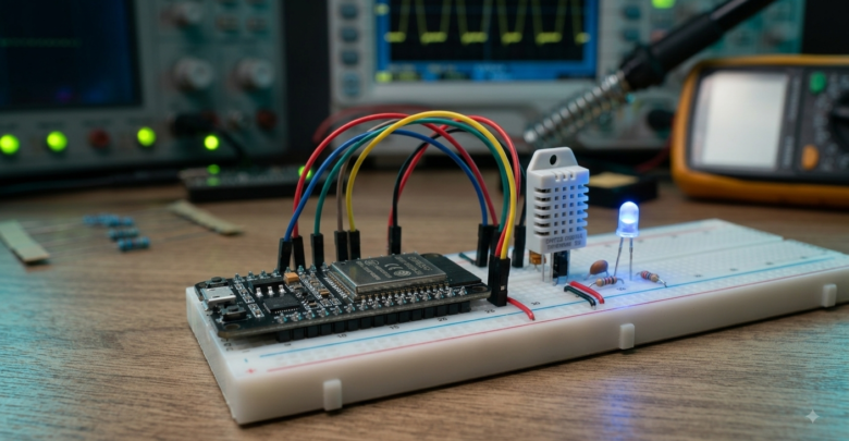
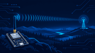
The ESP32 has become the undisputed backbone of modern Internet of Things (IoT) projects and embedded system developments. Designed and manufactured by Espressif Systems, this low-cost, low-power system-on-a-chip (SoC) integrates dual-mode Wi-Fi and Bluetooth capabilities, making it a significant upgrade over its predecessor, the ESP8266.
In this guide, we will explore the internal architecture of the ESP32, analyze its pinout configuration, and walk through a step-by-step practical implementation for real-world IoT deployment.
1. ESP32 Key Specifications and Technical Architecture
Before diving into hands-on code, understanding the hardware capabilities of the ESP32 chip helps in optimizing power consumption and processing efficiency.
- Processor: Tensilica Xtensa Dual-Core 32-bit LX6 microprocessor, operating at up to 240 MHz.
- Wireless Connectivity: Wi-Fi 802.11 b/g/n (up to 150 Mbps) and Bluetooth v4.2 BR/EDR & BLE.
- Memory: 520 KB SRAM, supporting external flash memory (typically 4MB to 16MB).
- Power Management: Multiple sleep modes, including Deep Sleep mode consuming as low as 10 µA.
- Peripherals: Capacitive touch sensors, ADC (Analog-to-Digital Converter), DAC, UART, SPI, I2C, and PWM outputs.
For detailed hardware datasheets and register mappings, refer to the official Espressif ESP32 Documentation.
2. Understanding the ESP32 Pinout and GPIO Assignment
Selecting the correct General Purpose Input/Output (GPIO) pins is critical to avoid bootloader lockups or unexpected hardware behavior.
       +-----------------------------------+
       |              ESP32                |
       |  [3V3]                     [GND]  |
       |  [EN]                      [VP]   |
       |  [GPIO 36/VP]              [VN]   |
       |  [GPIO 39/VN]              [34]   |
       |  [GPIO 34]                 [35]   |
       |  [GPIO 35]                 [32]   |
       |  [GPIO 32]                 [33]   |
       |  [GPIO 33]                 [25]   |
       |  [GPIO 25]                 [26]   |
       |  [GPIO 26]                 [27]   |
       |  [GPIO 27]                 [14]   |
       |  [GPIO 14]                 [12]   |
       |  [GPIO 12]                 [13]   |
       +-----------------------------------+
Safe GPIOs to Use
- Outputs & Inputs: GPIO 4, 16, 17, 18, 19, 21, 22, 23, 25, 26, 27, 32, 33.
- Input-Only Pins: GPIO 34, 35, 36 (VP), and 39 (VN). Note: These pins do not have internal pull-up or pull-down resistors.
Pins to Avoid During Initial Boot
- Strapping Pins: GPIO 0, 2, 5, 12, and 15 control the boot mode. Pulling these high or low externally during startup can prevent the chip from flashing or running code properly.
3. Practical Example: Building an HTTP Web Server with ESP32
To demonstrate its capabilities, let’s build a standalone asynchronous HTTP web server that reads temperature data and controls an onboard LED over Wi-Fi.
Prerequisites & Code Implementation
To compile this project, ensure you have configured the Arduino IDE or PlatformIO environment with the ESP32 board package installed.
C++
#include <WiFi.h>
#include <WebServer.h>

// Network Credentials
const char* ssid = "YOUR_WIFI_SSID";
const char* password = "YOUR_WIFI_PASSWORD";

WebServer server(80);
const int ledPin = 2; // Onboard LED

void handleRoot() {
  String html = "<html><body>";
  html += "<h1>ESP32 IoT Control Panel</h1>";
  html += "<p>Status: Active</p>";
  html += "<a href=\"/led/on\"><button>Turn ON</button></a> ";
  html += "<a href=\"/led/off\"><button>Turn OFF</button></a>";
  html += "</body></html>";

  server.send(200, "text/html", html);
}

void handleLedOn() {
  digitalWrite(ledPin, HIGH);
  server.sendHeader("Location", "/");
  server.send(303);
}

void handleLedOff() {
  digitalWrite(ledPin, LOW);
  server.sendHeader("Location", "/");
  server.send(303);
}

void setup() {
  Serial.begin(115200);
  pinMode(ledPin, OUTPUT);

  // Connect to Wi-Fi
  WiFi.begin(ssid, password);
  while (WiFi.status() != WL_CONNECTED) {
    delay(500);
    Serial.print(".");
  }

  Serial.println("\nWi-Fi Connected!");
  Serial.print("IP Address: ");
  Serial.println(WiFi.localIP());

  // Define Server Routes
  server.on("/", handleRoot);
  server.on("/led/on", handleLedOn);
  server.on("/led/off", handleLedOff);

  server.begin();
  Serial.println("HTTP server started");
}

void loop() {
  server.handleClient();
}
4. Best Practices for Industrial & Edge Deployments
When transitioning from breadboard prototypes to industrial environments, keep the following design considerations in mind:
- Power Decoupling: Place a 10µF capacitor near the
3V3andGNDpins to absorb current spikes caused by Wi-Fi transmission bursts. - Security & OTA: Implement HTTPS/TLS encryption and enable Over-The-Air (OTA) firmware update capability for remote maintenance.
- Hardware Watchdog: Enable the built-in Watchdog Timer (WDT) to automatically reset the microcontroller in case of infinite software loops.
For advanced edge computing integrations, check out our guide on Edge AI and Microcontroller Optimization Strategies.
Conclusion
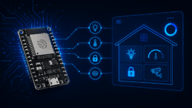
The ESP32 offers an incredible balance of performance, power efficiency, and price. Whether you are building smart home automation sensors or enterprise-grade industrial monitoring equipment, its robust feature set provides everything required for scalable IoT development.
#ESP32 #InternetOfThings #IoT #EmbeddedSystems #Arduino #Espressif #Microcontroller #SmartHome #Automation #TechTutorial #Electronics #EdgeAI #IoTJournal